| Honda
400EX Valve Adjustment Instructions
Time to adjust the valves on your 400EX? Interested
in doing it yourself? You have come to the right place!
Adjusting your own valves is within the capabilities
of anyone with basic mechanical knowledge. Please be
safe out there, be sure to follow all standard shop
practices (in other words, don't hurt yourself… if you
do, don't blame me!) I also highly recommend purchasing
a service manual. If you aren't completely sure that
you can do the job properly, either have a competent
friend show you, or take it to the shop and have them
do it for you. If you adjust the valves to tight (to
little clearance) then it is possible to burn a valve,
damaging the valve, and possibly the cylinder head.
You are probably wondering, "what tools do I need?".
1) metric socket's and various ratchets/extensions (I prefer 6 point sockets)
2) metric combination wrenches
3) metric allen wrenches
4) various screwdrivers (don't skimp, cheap philips screwdrivers do more harm than good!)
5) feeler gauges (make sure that the set includes both a .004 inch and .005 inch.)
6) a clean place to work, with good lighting
7) fire extinguisher, safety glasses, etc (hey, you never know)
Now that you have your tools assembled, lets get to work! Doing your own maintenance can be a very rewarding and fun part of ATVing, but remember to think safety! Before starting work I recommend thourghly cleaning the machine, and degreasing the motor. You don't want any 'stuff' falling in the motor, and a clean machine is much easier to work on.
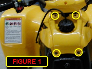
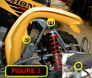
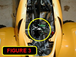
Start by removing the rear fender seat assembly. Unhook the negative battery cable and secure it where it can't accidentally fall into contact with the battery. This will prevent the motor from accidentally starting later on. With the rear seat/fender assembly out of the way, it's time to remove front plastic. The top tank cover comes off first. Start by removing the 4 plastic push pins [figure 1]. To remove the pins, pull the center section of the pin up about ½ inch. This unlocks the pin, allowing you to remove it. Remove the gas cap, and pull the cover towards the rear of the quad then remove it. Time for the front fenders to come off. Remove the 4 10mm bolts and 2 5mm allen bolts that secure the front fender assembly [figure 2]. Then pull the fender assembly forward slightly so that you can reach and disconnect the wiring for the headlights and ignition switch [figure 3].
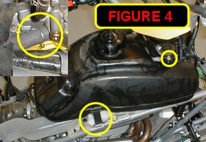
With the plastic out of the way it's time to remove the fuel tank. Turn the fuel valve off, and disconnect the fuel line from the carburetor. Put a rag underneath the line to catch the small amount of fuel that will drip out when you remove the line [figure 4]. Now remove the rubber strap on each side of the rear of the tank, and the 2 10mm bolts at the front of the tank and remove the tank from the bike.
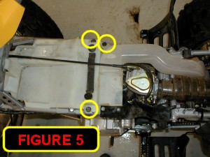
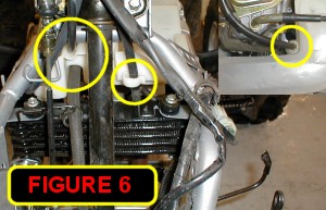
Time to remove the fuel tank heat protector. Start by unhooking the carburetor air vent, plastic push pin for the intake snorkel (you don't have to remove the snorkel though), clutch cable from the guide, and the 2 10mm bolts [figure 5]. Now you should be able to remove the heat protector from the frame. Make sure to pay special attention to the way the cables and vent hoses are attached to the fuel tank heat protector [figure 6] so you will be able to properly reinstall them.
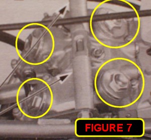
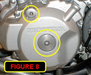
With a clear view of the cylinder head, it's time to get down to business. Remove the 4 valve adjustment caps from the top of the cylinder head [figure 7] and the 2 timing plugs from the left crankcase cover [figure 8]. You will need 6mm and 10mm allen wrenches to remove the timing plugs. Carefully inspect the o-rings on all the covers, if any are torn replace them to prevent oil leaks and/or crud from getting in the motor.
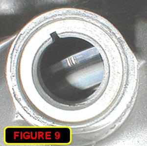
With the transmission in neutral slowly rotate the motor counter-clockwise. Use a 17mm socket on the crankshaft and rotate the engine, while watching the intake valves. (carburetor side). After the valve's start to close, slowly watch the small timing window until the mark with the T aligns with the notch [figure 9] (be careful, as there are several marks on the flywheel). After the mark with the T is aligned, there should be some play in all 4 of the rocker arms, if there isn't then continue rotating the engine until the T mark lines up again, and there is slack in all 4 rockers. This ensures that the motor is on the compression stroke. Never rotate the crankshaft clockwise, if you go past the mark, continue rotating it until the mark comes up again. The key things to remember are the T mark must be lined up, and there should be some play in all 4 of the rocker arms.
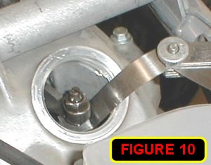
Time to adjust the clearance! Insert a feeler gauge between the rocker arm, and the sub-rocker arm [figure 10] Loosen the 10mm lock nut, and adjust the screw in or out until there is slight drag on the feeler gauge. Tighten the lock nut while holding the adjuster screw. After tightening the lock nut recheck the valve clearance to make sure the adjusting screw didn't move. The exhaust valves should have .005 inches of clearance, and the intake valves should have .004 inches of clearance.
With all 4 valves adjusted, replace the valve and timing covers, making sure that the o-rings are not torn. I usually put a small amount of oil on the o-rings so that they don't stick the next time I have to remove them. Put the rest of the machine back together by reversing the steps.
Finished? Grab a cold drink, and pat yourself on the back for a job well done!
|